Objects appear different depending on where the light source illuminating it is located. Shadows form at different locations. In this activity, we demonstrate a shadow model and extract shape from the shadows. Models depend on the type light source (point source, line source, etc.) used and where the light source is located. One of the more simple model is when the light source is placed at infinity. In general, when the light source is nearby, the brightness of an object illuminated by it is given by:
B(P) = [ρ(P)n(P)•S(P)]/R(P)2
where B(P) is the brightness of the object, S(P) is a vector from the light source and R(P) is the distance of the light source from the object.In an infinite light source, 1/r dependence of B(P) disappears and the vector S(P) becomes constant for every point in the object. Thus the equation becomes:
B(P) = ρ(P)n(P)•So
In capturing an image of an object, we assume that it is proportional to the brightness of the object:
I(x,y) = kB(x,y) = kρ(x,y)n(x,y)•So = g(x,y)•Vo
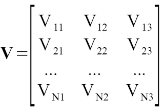
When an object is illuminated by light N light sources, Vo takes the form:where g(x,y) = ρ(x,y)n(x,y) and Vo=kSo.

Each row represents the position (x,y,z) of the source in 3D space. Given an image with its intensity equal to its grayscale value, we can determine g(x,y) using the equation above. If we took a N captures of the surface of object illuminated by N light sources, then for each point (x,y):
I1(x,y) = V11g1 + V12g2 + V13g3
I2(x,y) = V21g1 + V22g2 + V23g3
IN(x,y) = VN1g1 + VN2g2 + VN3g3
I2(x,y) = V21g1 + V22g2 + V23g3
IN(x,y) = VN1g1 + VN2g2 + VN3g3
or in matrix form:
I = gV
g = (VTV)-1VI
The normal vector can be solved by:

To get the surface elevation of point (u,v) on the surface, we use:
where
where
Below are the images taken for each light source locations.
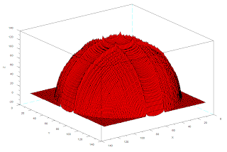
Using the procedure above, we obtained a 3D image of the surface shown in Fig.2.

Figure 2. 3D reconstruction of the hemisphere
Here, we have successfully reconstructed the image. The reconstruction, however, is not smooth. Some parts do not follow the contour of a hemisphere.
In this activity, I give myself a grade of 10 for a successful reconstruction of the surface.
I thank Irene, Alva, Orly for very very useful help. :)
In this activity, I give myself a grade of 10 for a successful reconstruction of the surface.
I thank Irene, Alva, Orly for very very useful help. :)


No comments:
Post a Comment